CARBURETOR SYNCHRONIZATION AND IDLE ADJUSTMENT
Proper
carburettor synchronization and idle adjustment requires an exhaust gas
CO meter, a rev-counter and a four-column mercury manometer.
Proceed as follows:
If all the above-mentioned equipment is not available, it is still possible to obtain the correct idle setting by simply resetting the idle speed screw (2) at the balance adjusting screw (4).
DHLA 40-45-48
Applications:
ALFA ROMEO
1300- 1600 Giulia Super
1600 GT Coupe’ - 1750 Saloon
2000 Saloon - GT Coupe’ - Spider
LOTUS CARS
Europa Twin-cam - Elan -
Elan Plus - 2S
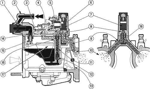
1. FEATURES
2. OPERATION
a - Starting
Fuel
at the union (2) passes through the filter (1) and reaches the seat
(14) where the needle (15), attached to the float (17), controls the
fuel flow into the float chamber thereby maintaining a constant level.
The float chamber is vented to the atmosphere through the vent (4) in
the chamber. On opening the choke valve (7), fuel metered through the
starter jet (12) passes into the emulsion tube (11) where it is mixed
with air from the channel (16) and then enters the passage (6) further
mixing with air from the vent (5) and reaches the valve chamber. From
here, it is distributed via the two ducts (9) which lead into the main
barrels (10) downstream of the throttles. On closing the choke valve,
communication between the main barrels and the starting circuit is
broken as well as communication between the two barrels due to the
sealing action of the split bushing.
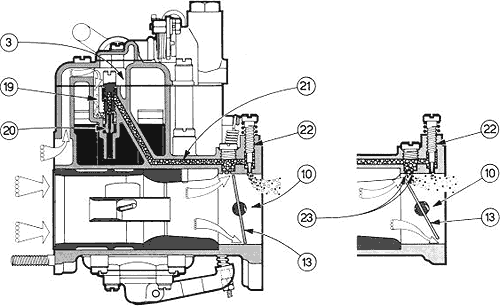
b - Idling
Fuel
from the float chamber is metered through the idle jets (20) and mixes
with air from the well (3) through the channels (19). Mixture through
channels (21) reaches the idle mixture screws (22) and, when regulated
by them, reaches the main barrels (10) downstream of the throttles (13).
c - Progression
On first opening the throttles (13), that is, when passing from idling to
full throttle, mixture also reaches the two barrels (10) through the
progression holes (23).
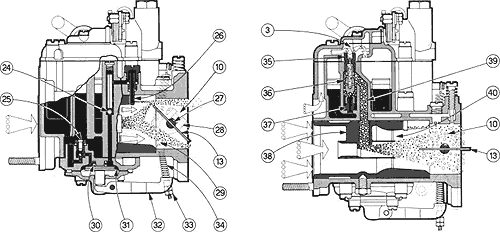
d - Acceleration
On
opening the throttles (13), the lever (28) attached to the throttles
spindle (27) by means of the rod (29) and spring (34) pushes the pump
lever (32) which acts directly on the pump diaphragm (31) which is
normally held out by the spring (30). The pump diaphragm then pumps
fuel into the two main barrels (10) via two separate channels through
the delivery valves (24) and the pump jets (26). On closing the
throttle, the diaphragm returns to its Full position pushed by the
spring (30), drawing fresh fuel from the float chamber through the
inlet valve (25). The nuts (33) adjust the pump injection quantity.
e - Full throttle
At full throttle, fuel from the float chamber is metered through the main
jets (37) entering the wells (36) and mixing with air metered through
the air corrector jets (9). This mixture then passes through the
channels (39) to reach the auxiliary Venturi (38) where it is further
mixed with air drawn into the main intake and finally flows into the
Venturi (40) to reach the barrels (10).
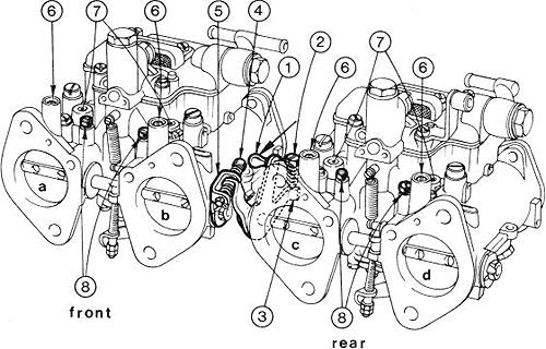
3. ADJUSTMENT
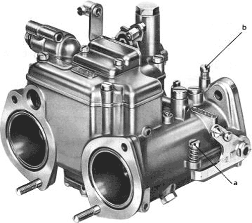
a - Idling
Always
adjust the idle with the engine hot, screwing in the idle speed screw
(a) to obtain a slightly higher idle speed than normal. Then adjust the
mixture adjusting screws (b) until you find the most even running;
remember that unscrewing them results in a richer mixture and vice
versa. Then steadily unscrew the idle speed screw again until the
normal idle speed is reached.
b - Accelerator pump
Adjust
the accelerator pump injection quantity by fitting the carburettor to
the special support with the proper gasket and connect the carburettor
to a reservoir so that it is continuously supplied with fuel.
Put
the two graduated measuring tubes, each having a capacity of 10 cc,
under the drain pipes on the support in order to collect all the fuel
pumped out. Open and close the throttle completely 20 times, with a few
seconds’ break in between each time, and check that the amount of fuel
collected in the tubes corresponds with the correct specification and
is the same for both barrels. It not, adjust the pump delivery by
resetting the nut and locknut fitted on the pump operating rod;
remember that screwing the nuts up increases fuel delivery and vice
versa. It there is any difference in volume between the two barrels,
remove the pump jets and blow through them vigorously to correct this.
Recheck until the correct setting is obtained and then ensure that the
nut and locknut are retightened.
c - Float level
Check
that the float has the actual weight which is marked on it, is
undamaged and also tree to rotate on its pivot pin. Hold the
carburettor cover vertically so that the float arm is in light contact
with the needle and with the spring in the needle not compressed. In
this position, check that both half-floats are at the correct distance
from the float chamber cover measured to the top cover gasket fitted to
it.
| float | A | 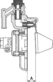 |
| 7298.1 7298.2 | 14,5 ÷ 15 16,5 ÷ 17 | |
4. MAINTENANCE
To keep the carburettor in good condition, especially after operating faults have occurred, proceed as follows. Dismantle the carburettor, washing the components in fuel and blowing dry. Special care is needed with the jets, emulsion tubes, needle valve seat, fuel tilter and all the drillings in the carburettor body. Check the condition of all the components before reassembling and replace them wherever necessary only with new parts. When reassembling the carburettor, renew all the gaskets and O -rings.